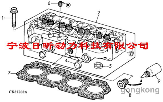
- 型号:3029/4039/4045/6068/6081/6125
- 数量:100
- 制造商:宁波北仑日兴动力科技有限公司
- 有效期:2020/7/1 0:00:00
温馨提示
宁波日昕动力科技有限公司建立了一套完整的美国强鹿JOHN DEERE柴油机、柴油发电机零配件供应体系,全天候快速响应,纯正的美国强鹿JOHN DEERE柴油机、柴油发电机配件是您最佳的选择,因为您所得到的是延长美国强鹿JOHN DEERE柴油机、柴油发电机动力系统寿命的最佳保证。
特别声明:我司只销售强鹿JOHN DEERE柴油机、柴油发电机原厂配件,需付厂或防品件请绕道,谢谢。
强鹿JOHN DEERE柴油机配件有:活塞环喷油器滤清器修理包燃油泵油封节温器燃油管水管仪表电器螺栓螺母活塞冷却喷咀凸轮轴衬套皮带软管连杆瓦主轴瓦齿轮机油油嘴 PT泵配件 抱箍卡箍 调速板 电控板 气门 缸盖 活塞 缸套 连杆 曲轴 缸体 排气管 水箱 空压机 机油冷却器 机油盘 中冷器 热交换器 风扇 充电机 起动马达 齿轮室盖 辅助驱动 减振器 飞轮壳 飞轮 摇臂 凸轮从动件 增压器 机油泵 海水泵 水泵 润滑油 油咀 油泵 滤清系统 涡轮增压器 PT燃油泵 滤芯 支架 隔套 进气管 皮带轮 机油尺管 油管 防护罩 接头 密封圈 紧固件 垫片等配件
约翰迪尔美国强鹿JOHN DEERE全系列产品型号有:3029DF128、4039DF008、4045TF258、6068TF158、6068TF258、6068HF158、6068HF258、6081HF001A、6081HF001B、6125HF070A、6125HF070B、6125HF070C。
John Deere约翰迪尔强鹿柴油发动机气缸盖和阀门的修理和调整
Check Valve Lift Serial Number
( —199,999)
RG5789 –UN–09AUG91
Checking Valve Lift
IMPORTANT: For a more accurate measurement, it is
recommended that valve lift be
measured at 0.00 mm (in.) valve
clearance and with engine COLD.
NOTE: Measuring valve lift can give an indication of wear
on camshaft lobes and cam followers or bent
push rods.
1. Remove turbocharger oil inlet clamp and rocker arm
cover. Loosen lock nut on rocker arm. Set valve
clearance at 0.00 mm (in.) on valve being checked.
Tighten lock nut.
2. Put dial indicator tip on valve rotator. Be sure that
valve is fully closed.
3. Check pre-set on dial indicator. Set dial indicator
pointer at zero.
4. Manually turn engine in running direction, using the
engine rotation tools previously mentioned for checking
valve clearance.
5. Observe dial indicator reading as valve is moved to
fully open position. Record reading and valve number.
Specification
Intake Valve—Lift 13.53—13.71 mm
(0.533—0.540 in.)
at 0.00 mm (in.)
..........................................................
Wear Tolerance 12.65 mm (0.498 in.)
at 0.00 mm (in.) clearance
........................................................
Exhaust Valve—Lift 14.52—14.70 mm
(0.572—0.579 in.)
at 0.00 mm (in.)
.......................................................
Wear Tolerance 13.64 mm (0.537 in.)
at 0.00 mm (in.) clearance
........................................................
6. Repeat procedure on all remaining valves.
7. Reset valve clearance to specification after measuring
lift. See CHECK AND ADJUST VALVE CLEARANCE
SERIAL NUMBER ( —199,999) earlier in this group.

John Deere约翰迪尔强鹿柴油发动机拆下气缸盖
Remove Cylinder Head Serial Number
( —199,999)
A—Coolant Manifold
B—Turbocharger
C—Intake Manifold
D—Exhaust Manifold Assembly
It is not necessary to remove engine from machine to
service cylinder head on all applications. Refer to your
Machine Technical Manual for engine removal procedure,
if required.
CAUTION: After operating engine, allow exhaust
system to cool before working on engine.
DO NOT drain coolant until the coolant
temperature is below operating temperature.
Always loosen drain valve slowly to relieve any
excess pressure.
1. Drain engine oil and coolant. Disconnect turbocharger
oil inlet line at turbocharger or oil filter base. See
DISCONNECT TURBOCHARGER OIL INLET LINE in
Group 010.
NOTE: If cylinder head is being removed for piston and
liner repairs or any other service that does not
require disassembly of head, cylinder head can be
removed with coolant manifold (A), turbocharger
(B), intake manifold (C), and exhaust manifold (D)
installed.
2. Remove coolant manifold and all coolant piping. See
REMOVE COOLANT MANIFOLD in Group 070.
3. Remove turbocharger. See REMOVE
TURBOCHARGER in Group 080. Remove front and
rear exhaust manifold (D). See REMOVE, INSPECT
AND INSTALL EXHAUST MANIFOLD in Group 080.
4. Remove air intake manifold. See REMOVE, INSPECT
AND INSTALL INTAKE MANIFOLD in Group 080.
5. Remove fuel injection delivery lines and injection
nozzles. If mechanical fuel system, see REMOVE
FUEL INJECTION NOZZLES in Group 090 of
CTM243. If Level 3 Electronic fuel system, see
REMOVE FUEL INJECTION NOZZLES in Group 090
of CTM134.

6. Remove rocker arm cover with ventilator outlet hose
assembly.
7. Loosen all rocker arm adjusting screws before
removing assembly.
8. Remove six cap screws and remove all four rocker arm
shaft clamps (A). Lift rocker arm assembly (B) up and
remove. Remove wear caps from valve stems.
9. Remove all 12 push rods and identify for reassembly.
NOTE: Clean and inspect push rods. See CLEAN AND
INSPECT PUSH RODS SERIAL NUMBER ( —
199,999) later in this group.
A—Rocker Arm Shaft Clamps
B—Rocker Arm Assembly
10. Remove all 26 cylinder head cap screws. Discard cap
screws, they are not reusable.
IMPORTANT: DO NOT use screwdrivers or pry bars
between cylinder block and cylinder
head to loosen head-to-block gasket
seal.
11. Lift cylinder head from block. If cylinder head sticks,
use a soft hammer to tap the cylinder head.
12. Remove cylinder head gasket. Inspect for possible oil,
coolant, or combustion chamber leaks. Also, check for
evidence of incorrect or defective head gasket being
used.
NOTE: Do not rotate crankshaft with cylinder head
removed unless all cylinder liners are secured
with cap screws and large flat washers as
described in Group 030. See REMOVE PISTONS
AND CONNECTING ROD ASSEMBLIES in Group
030.
- 电话:15088860848 0574-26886646
- 传真:0574-26892499
- email:ygx556@163.com

手机扫描二维码分享本页

工控网APP下载安装

工控速派APP下载安装
| 评价: | 一般 | ||
 约翰迪尔强鹿柴油发动机气缸盖和阀门的修理和调整


